The last few months I’ve been working intensively on a complete workflow for detailed design of concrete bridges with Autodesk Revit. In case you would ask me “Is Revit even capable of designing bridges with a high level of detail?” Well, my answer would be “Definitely YES !” And I would like to share you the results in what is probably my longest post ever on this blog. So take your time to read it…
Introduction
Before I start explaining, maybe some background first. Some months ago, I needed to develop a POC of bridge design with Revit for some important customer meetings. In the past you might have seen already a solution from my colleague at Autodesk, Matthias Stark, which he explained in this class at AU 2015. Also Simon Moreau, author of the BIM42 blog based himself on this method in this post. So first of all, thank you Matthias and Simon for the inspiration. The workflow below is a consolidation of Matthias his method and the method I already used previously. The result is an easy to use flow, applicable on any type of concrete deck or box bridges or even concrete tunnels, using some Dynamo scripts that I have predefined for your personal use. All the data referred to can be downloaded at the bottom of this post.
Workflows
The full workflow from conceptual road/bridge design until detailed bridge design consists of 16 steps, which are all explained in this YouTube playlist “Concrete Bridge Design to Fabrication Workflow”. The image below shows a global overview on this workflow. This is a representation of what is possible currently possible with our solutions at Autodesk, and shows a positioning of the products for each phase.
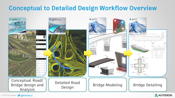
- The conceptual road and bridge design can be done using Infraworks 360.
- This Infraworks model is then imported in AutoCAD Civil 3D for further detailing of the road design.
- The data, built up in AutoCAD Civil 3D, is then reused in Revit and Dynamo (by means of Feature Lines, Corridor Points reports, …) to get the detailed bridge design.
- Finally the bridge rebar detailing and design documentation are further processed in Revit.
This workflow is also setting the base for extended construction workflows. As all the concrete bridge design data is stored in the Revit model, it can be used in Construction Management (sequencing, quantification, clash detection) and Project Delivery Management. This involves BIM360 Glue, BIM360 Field, Navisworks Manage, BIM360 Docs,… An overview of the possible workflows can be found in the Bridge Design to Fabrication Workflows.pdf file which is included in the datasets at the bottom of this post.
So, this post is limited to the design steps with the creation of the superstructure deck family and the distribution of transversal rebar in the deck.
BRIDGE SUPERSTRUCTURE CREATION
Before building this family, I listed up some requirements which the bridge deck family should meet.
- The superelevation, width and thus also the slope for each lane are calculated from the Civil 3D data.
- The family needs to be flexible and modifiable afterwards in the Revit project.
- The Dynamo script used for the creation should be as small as possible and should be generic to use with other bridge sections or even tunnels.
- The family should be built up that way that it can host annotations in 2D Section views (even if the section goes through a curve).
- The family needs to be able to host rebar.
- The Dynamo script needs to be able to handle any orientation of a bridge (seen in a planview), in any position of a circle quadrant.
Meeting these requirements, this method differentiates from current methods existing already on the internet.
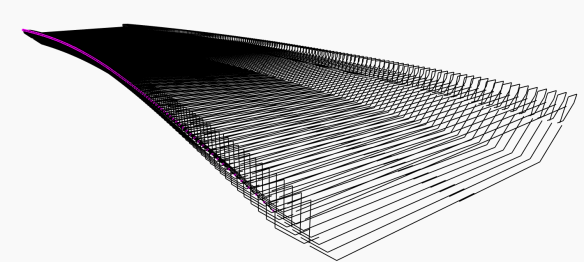
As you will see in this part of the playlist, the superstructure is created based on Civil 3D Corridor points and a Mass family representing the section profile of the deck. This “profile” is placed within the Revit main “Concrete Deck” family and then lofted to get a solid geometry.
Prerequisites
Before you start trying this yourself you need to install the package BIM4Struc.BridgeDesign through the Package Manager in Dynamo.
The Dynamo script “01 Bridge Superstructure Creation.dyn” used for this, is included in the datasets at the bottom of this post.
Step 1 – Extract Civil 3D Corridor Points
The geometry of the bridge deck should be based on the solid geometry of the road, which is designed in AutoCAD Civil 3D. Important is that the slopes of each lane of the road can vary along the road length (ie. from -2.5% to +2.5%). This information is extracted from Civil 3D using the “Corridor Points Report” and this data is stored in an Excel sheet. In this method it needs points for the Top Left, Top Right and Top Center edges of the road. Using Marker Points in Civil 3D you can give your own names to these points. This step is explained in this video.

Note: the reason why I used the Corridor Points Report and not just Feature Lines as an imported geometry in Dynamo, is explained in the reactions on this post (click on the balloon next the post title).
Step 2 – Create the section profile
As part of the “mise-en-place” you also need to create a family representing the section profile of the deck (T-deck, box girder or even tunnel). This is based on a “Metric Mass” family template. Make sure you create parameters for the superelevation, lane width and slope at the right and left of the road. As shown at 1:10 in this video, the values for the superelevation are recalculated within the family in order to handle positive and negative values.
After saving this family (“Concrete Deck Profile.rfa”), you load this one into a new family based on the “Metric Generic Model Adaptive.rft” template. You can change the behavior of this family in the Family Category & Parameters dialog. From there on we will use Dynamo to create the geometry.
Step 3 – Reading road data into Dynamo
Now we can start combining the information from step 1 and 2. This step starts at 2:11 in this video. The information about the road geometry can be read into Dynamo as a starter. The custom node “Road Splines from Excel” from the BIM4Struc.BridgeDesign package helps reading this Corridor Points report, by indicating the proper column indexes and Point Code descriptions (i.e. “RoadTopLeft”). If you choose to name these points differently in the Civil 3D model, then you need to change their descriptions as well in the Dynamo script.
In case the data changes in Civil 3D, you just need to regenerate the Corridor Points Report to Excel and rerun the script.
 The result of this operation are 4 3D Polycurves representing the road top edges (left, right and center) and also the projection of the centerline at level 0 m. These lines will be used later to calulate the superelevations (lane slopes) at specific intervals.
The ConversionMultiplier can be used to convert the units. By default it is set to 1000 to convert the metric “m” used in the Civil 3D model to “mm”, which is the unit used in the Revit project.
Note that within the custom node, the coordinates are reset to the internal Revit origin, this to avoid the geometry being positioned at geographic coordinates in a Family. To achieve that, the coordinates of the start point of the centerline are set to 0, while the other coordinates are recalculated relatively to that point. Afterwards this will make it easier to position the bridge deck family in the Revit project (i.e. based on the imported feature lines in Revit).
Step 4 – Setting the bridge deck parameters in Dynamo
Before continuing with the geometry we need to setup the bridge parameters:
- Bridge Alignment Variables:
This group allows to add an offset and/or skew angle to the first and last profile of the bridge deck. These values are further on used to divide the alignment lines. - Bridge Superstructure Section Definition
The configuration of this group depends on the way the “Concrete Deck Profile” family is created. In this optional part you can set the type parameters of the nested family, before it is placed.
Step 5 – Generating the bridge deck geometry with Dynamo
Starting at 3:25 in this video a second custom node is brought into the script. The node Bridge Section Profile Placement from the BIM4Struc.BridgeDesign package will place the initially created “Concrete Deck Profile” family at the right positions and orientation. The node is built in a way it doesn’t matter in which quadrant of a circle the planview of the bridge is positioned and orientated. It will adjust the profiles accordingly. Practically this means that the centerline points can have coordinates with syntaxis (-x,-y), (-x,y), (x,y) and (x,-y).
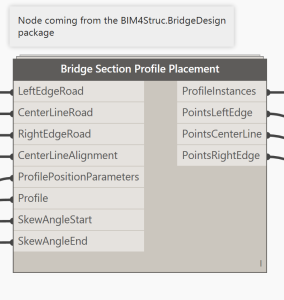
This custom node needs the Polycurves from the road and the centerline at level 0 m as inputs. The ProfilePositionParameters port needs a list with values between 0 and 1 indicating the positions of the profile. The more elements in the list, the more accurate the curvature of the horizontal alignment. But don’t exaggerate as this influences the number of section profile instances placed in the family (and thus makes it heavier). Next you also connect the proper family type (Concrete Deck Profile.rfa in this case) to the Profile input port. And the skew angles at start and end can be indicated as well.
The outputs of this node return the ProfileInstances placed in the Revit family as well as the generated points on each road edge in Dynamo. The ProfileInstances are used in Step 7, when we need to integrate the calculated values from Step 6 into the Revit family.
Important to know is that in this step only the position and orientation of the section profiles are handled. The results of the generated points (bottom 3 output ports) are further used in Step 6 to define the individual section dimensions.
Step 6 – Calculate dimensions of each section profile
Now we know the coordinates and orientation of each division point on the road edges in Dynamo, we can calculate the values of the superelevation and thus also the width and slope of each road lane. This is shown starting from 4:26 in this video.
 The procedure to calculate doesn’t need to be changed as long as you use the ‘three edge method’ to detect the road geometry. If your section profile uses different parameters names for the Lane Width and Lane Slope, then off course you need to change their references in the Dynamo script in the middle Code Block shown in the image above.
Step 7 – Modify profile instances and create geometry
The results of the parameter calculations in Step 6 are connected with the Element.SetParameterByName node, and this will make the proper changes to each individual section profile placed in the Revit family. The geometry of the section profile instances is send back to Dynamo (Element.Curves) and used to create the solid deck geometry by means of the Form.ByLoftCrossSections node. Starting at 4:50 in this video.
 I’ve decided not to group all these parameter calculation and solid creation nodes into a custom node, as it might happen that you use a different set of parameters, instances, … This way, the script is flexible for you to change if needed.
Step 8 – Flexible and modifiable family
The last section of this workflow (starting at 5:52 in this video) may be the most important one. After the Dynamo script has run and been closed, it is still possible to change the properties of the section profiles (in red) – which are by the way placed in a different subcategory for better visualization management in the project.
When you connect the instance parameters of the nested “Concrete Deck Profile” family with the family parameters of the main deck family, then you make it even possible to change the dimensions of the deck geometry from within the Revit project.
ADDING STRUCTURAL REBAR TO THE BRIDGE DECK
I think we all can agree that a concrete bridge deck geometry without reinforcement details added is like a pub without beer…
This part of the workflow will give you some insight in the possibilities that Dynamo offers to Revit when modelling complex rebar cages into the curved deck. There are many methods to achieve this, and there are also lots of varieties in the rebar shapes. The method described below is a generic usable one for the modelling of the transversal rebar cages, and is based on a “distribution along path” principle.
 The results are shown in this video from the playlist. In the next steps, it is described how to get to this result.
Prerequisites
The method used here needs the BIM4Struc.Rebar and Dynamo for Rebar packages to be installed in Dynamo.
The Dynamo script “07 Transversal Rebar Distribution.dyn” used for this, is included in the datasets at the bottom of this post.
Step 1 – Model a base set of reinforcement
Before you start it is necessary to have modelled a base set of transversal reinforcement in the bridge deck. This can be done with the out-of-the-box Revit tools. This base set has the right properties already. Optionally you can save the rebar objects in a Selection Set in Revit, in order to find it back easily after distribution and to delete it then. (See 0:17 on this video)
Step 2 – Import the base rebar geometry in Dynamo
This base set of rebar objects will be used to generate a distributed set of rebar. Therefore we need to read the original geometry of the rebar elements into Dynamo. This is done in the “Get Rebar sketch from Revit” group, by means of the Rebar.GetCenterlineCurve node (from the BIM4Struc.Rebar package). The node returns the sketch behind the 3D Rebar object in Revit. (Read the input port tooltips on the node for more information about the options). The resulting curves can now be used to be distributed within the deck geometry. In the same time the Revit ID of the object hosting the base rebar is read too, to use it further in the Rebar creation step.
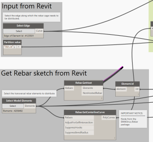
(From 0:25 on this video)
Step 3 – Define position and orientation of base rebar
This step is needed to detect the right orientation of the base rebar set and its relative position to the selected distribution path (Select Edge from Step 2). This information is crucial to make the distribution working. The position and orientation is represented then by the Curve.CoordinateSystemAtParameter node
Step 4 – Distribute the rebar sketch lines in Dynamo
The geometry from Step 2 combined with the position and orientation data from Step 3, results in a new list of geometry representing the equally distributed rebar sketch lines.
Step 5 – Create Rebar geometry in Revit
Finally (as seen at 0:59 on this video), the resulted curves are used to create the Rebar objects in Revit, with the Rebar.ByCurve node from the Dynamo for Rebar package To use the same properties for the newly created Rebar, the properties from the selected base set are read by the Rebar.GetProperties node from the BIM4Struc.Rebar package.
MORE DYNAMO FOR REBAR ?
The datasets below contain more scripts to create the longitudinal reinforcement i.e.
The described method above, together with some more “rebar awesomeness” will be presented and explained more in detail in this class at AU 2016 in Las Vegas, later this year.
DATASETS
The datasets used in this workflow can be downloaded here.
I hope you enjoyed reading and that this workflow may be of use for your daily work !




Hi Dieter,
Very nice write up, thanks!
I wanted to chime in to give you another option for step 1. Instead of using a coordinate table you can also create Feature Lines in Civil3D using the feature line tools, and pick the bridge alignment and edges. You can now explode those feature lines which will end up as 3D polylines. Save those polylines to a new DWG, import the DWG into Revit and make sure you place the DWG in an in-place Family or Mass. You can now use the Element Selection tool in Dynamo and pick the family to end up with the line geometry and use that for the profile placement.
Regards,
Joost Schlebaum
Hi Joost,
You’re right. I used this approach initially. But there are a few downsides with the Feature Lines method:
1. When bringing the feature line geometry from Revit to Dynamo, the index of the imported curves is not fixed in the list, per project (ie. Right = 0, Left = 1, …). Which means you have to find manually their index for each new project. With the Corridor Points Report, you can define the right order already from withing the Civil 3D model.
2. Exploded Feature Lines can cause 0-segments in the 3D DWG Polycurve. When importing in Revit, these segments are eliminated, but the number of vertices will be different too then. This can cause small inaccuracies when detecting the lane width based on the line geometry in Dynamo.
3. Most important is “how to deal with changes?”. When the Civil 3D corridor and thus the feature lines are updated, you need to rework lots of steps: explode Feature Lines, reimport geometry in Revit, and again track the geometry indexes in Dynamo. With the Corridor Points Report it is sufficient to regenerate the Excel export and rerun the script.
Though, the Feature Lines are used in the project, so it can be used for the “Automatic Bridge Elements Placement” script, so you can easily find the origin of the bridge deck in the project.
Hi Dieter,
Thanks for your reply.
Very good points indeed. Number 3 is as well of most importance to me.
What I like about the exploded feature line method is that its a little more visual. What you see is what you get. When I use Civil3D for double curved tunnels for example I like to use corridor sections to create gaps for the joints and dilations. The pro of using featurelines/3D polylines is that instead of heaving a number of coordinates on a fixed distance, you have the fixed start-, end- and midpoints of each line element which are very usefull when creating objects like joints and dilatations. Its true, I am not really sure if the pro’s outweigh the cons on this one.
I did measure the small inaccuracices once and didn’t really found them to be that more inaccurate/of an issue compared to the fixed distance coordinates.
But to be fair, after attending Matthias’ great session at the last AU I use the coordinates method for 95% of the time. The “dealing with changes” being my biggest factor (and working with numbers instead of lines is ofcouse more hipster ;-))
Thanks again for this great write-up! I really hope we are going to see a movement towards such a workflow in the little conservative infrastructural world
Hi Dieter
I learn a lot by following your blog and lessons at Autodesk Unversity about rebar and bridge modelling by using dynamo.
I want to learn if you know a way for modelling variable deck ection height by using same package at dynamo dicussed in your post.
Thank you very much
Hi Göksel,
Thanks for your feedback. What you’re asking is perfectly possible with this package yes. And you don’t have to change that much. What you have to do is:
1) Create a parametric family containing the section of your deck (like shown in the movies). In that family you add a parameter that drives the section height.
2) Use the script from the post and add a range of values for your deck height to the code block where the parameters of the section profile are changed (Left Lane Width, …)
Remarks:
– You need to know the deck height at each position of the profile.
– In case you’re dealing with an arc shaped box girder, and you know the start height, middle height and end height, then you need to use some interpolation to detect the deck height at the specific profile position (station location).
Cheers,
Dieter
Hi Dieter!
This is one of the best workflows and smartest use of Dynamo I’ve seen.
I am currently working with it changing some little details here and there but It is great.
I would like to ask you if you think that it is reasonable to try to automate the abutment placement as well? Is it worthy doing it?
Hi Dieter, Excellent workflow.
I have one doubt, how much time did you take to do this proyect? and how many people working with you?
Hi Alejandro,
Glad you like the workflow. It took a bit of time. I guess about 2 weeks effective time to create the workflow. And some time to do some research, which is a one-time operation. As for the design part I did this on myself. But the thing is that with the script that generates the deck and that positions the columns, are generic ones. This means that they can be used for other concrete bridges, as long as you have an alignment and one or more sections of the bridge. Besides that the script can be used for tunnel design as well on the same basis. So, the time that has been put upfront in this, returns time savings in other projects…
Dear Dieter Vermeulen,
Creation of 3D reinforcement in concrete bridge deck using Revit Dynamo is a method to learn for engineering companies, especially with double curved deck. I have created a simple bridge to learn and apply your Dynamo code cf. http://icdas.dk/viewpage.php?page_id=406. Dynamo has perfectly created the concrete geometry of the double curved bridge. I add then structural rebar in the next section. Dynamo has also successfully created rebar corrected in Floor Plans Site View. Unfortunately, the vertical positions of the rebar are inaccuracy. I have made several tests but not find the reason yet. It will be wonderful if you can give me an explanation. Please mail me so I will send you the Revit file and my website for descriptions of the errors.
Best regards,
Truc Huynh, ICDAS Founder
External Lecturer, Technical University of Denmark
Hi Dieter,
many thanks for sharing this workflow !
can you help me with the Revit 2016 version datasets required for this workflow ?
Thank you so much in advance.
Best regards,
Emil.
Hi Emil,
The datasets are not available for Revit 2016. However, the Dynamo scripts can be used to create new bridge content in 2016.
Hi Dieter,
Workflow etc is brilliant, however I’m getting an issue when using it. I have a corridor report from C3D from another colleague, the script will place the points correctly etc however the profile is not updating to match the slopes.
Hi Arron!
Try changing the two last lines of the Code Block that calculates the slopes of the profile with these:
SlopeLeft=Math.Round(Math.Atan(SupLeft/LaneWidthLeft),1);
SlopeRight=Math.Round(Math.Atan(SupRight/LaneWidthRight),1);
I had the same problem and it is because the slopes that Dynamo calculates are in ” % ” but Revit wants to know the value in ” ° ” when setting the parameters.
I hope that resolves your issue 🙂
Cheers,
Pablo MELERO
Hi Dieter !
First of all, congratulations for this excelent workflow!I’ve been working on the bridge design with Dynamo this
week basing my work on your solution and on Matthias Stark class at AU. I want to give you a little feedback concerning the skewness:
With this procedure, the last section profile (who has been rotated) don’t get the good dimensions. That is because Dynamo can’t calculate the width of one of the lanes because it can’t find the intersection between the rotated plane and the edge of the one of the corridors, so it takes the value of the last section. And the result is a bridge with the start (or end, or both of them) completly deformed.
To solve this problem, I think the better way is to generate the bridge without skewness and after to cut the solid at the desired station with an angle. I worked on it but I have issues cutting the result of “Form.ByLoftCrossSections” node. In Revit, the cutted bridge and the original one are superposed even if the “Form.ByLoftCrossSections” node is Unable. I’ll keep working on it but any idea is welcome 🙂
Maybe this post will be a little tricky to understand without photos, I’m sorry about that !
Regards,
Pablo MELERO
Great post, really good to see the full workflow and follow along with the dataset.
How did you position the flyover and the tunnel objects in the correct location after they were created as generic family elements?
I can import the 3d alignments in .dwg as a guide, but I’m hoping there is a better way?
Hi Gerald, the positioning is done through the import of the Corridor Points report. They define the exact coordinates of the bridge elements.